This page provides detailed information on the MAX7219CNG LED display drivers, including the MAX7219CNG Pinout Diagram, pin configuration, pin description, schematic, and functional diagram. Essential for engineers working with LED displays.
1. MAX7219CNG Pinout Diagram
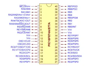
The MAX7219CNG pinout diagram is key for understanding device connections.
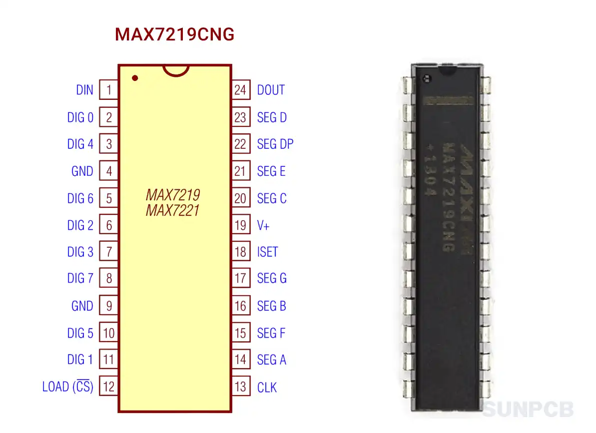
MAX7219CNG Pinout Diagram (Page 1 of 17)
![]() MAX7219CNG pinout diagram pdf download (P1/17)
MAX7219CNG pinout diagram pdf download (P1/17)
2. MAX7219CNG Pin Configuration and Description
Check the table below for MAX7219CNG pin configuration and detailed pin descriptions.
| Pin# | Pin Name | Pinout Description |
|---|---|---|
| 1 | DIN | Serial-Data Input. Data loads into the 16-bit shift register on CLK's rising edge. |
| 2 3 5 8 10 11 |
DIG 0 DIG 4 DIG 6 DIG 7 DIG 5 DIG 1 |
Eight-Digit Drive Lines. Sink current from the display common cathode. MAX7219 pulls outputs to V+ when off; MAX7221 drivers are high-impedance when off. |
| 4,9 | GND | Ground. Both GND pins must be connected. |
| 12 | LOAD (MAX7219) / CS (MAX7221) | Load-Data Input (MAX7219): Latches last 16 bits on rising edge. Chip-Select Input (MAX7221): Loads data while CS is low, latches on rising edge. |
| 13 | CLK | Serial-Clock Input. Max 10MHz. Data shifts in on rising edge, out on falling edge at DOUT. For MAX7221, active only when CS is low. |
| 14 15 16 17 20 21 22 23 |
SEG A SEG F SEG B SEG G SEG C SEG E SEG DP SEG D |
Seven Segment Drives and Decimal Point Drive. Source current to display. MAX7219 pulls to GND when off; MAX7221 drivers are high-impedance when off. |
| 18 | ISET | Connect to VDD via resistor (RSET) to set peak segment current. See RSET selection section. |
| 19 | V+ | Positive Supply Voltage. Connect to +5V. |
| 24 | DOUT | Serial-Data Output. Data from DIN appears here after 16.5 clock cycles. Used for daisy-chaining, never high-impedance. |
3. MAX7219CNG Typical Application Circuit Diagram
This diagram shows how to connect MAX7219CNG to a microcontroller and LED display. Vital for correct setup.
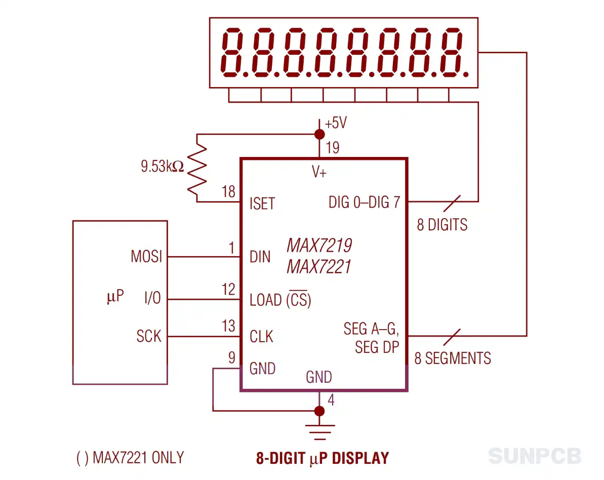
Typical Application Circuit of MAX7219CNG (Page 1 of 17)
![]() MAX7219CNG typical application circuit diagram pdf download (P1/17)
MAX7219CNG typical application circuit diagram pdf download (P1/17)
4. MAX7219CNG Functional Block Diagram

The MAX7219CNG block diagram highlights internal workings:
- Serial Interface: Links to microcontrollers.
- Shift Register: Holds incoming data.
- RAM: Stores digit data.
- Decoder: Turns data into segment patterns.
- Drivers: Manage LED current.
See page 5 for details. ![]() MAX7219CNG functional block diagram pdf download (P5/17)
MAX7219CNG functional block diagram pdf download (P5/17)
5. MAX7219CNG Maxim Integrated Overview
5.1 Description
The MAX7219 and MAX7221 are compact, serial input/output drivers for common-cathode LED displays. They support up to 8 digits, bar graphs, or 64 LEDs with on-chip BCD decoding and RAM.
5.2 Overview
The MAX7219CNG simplify driving LED displays by managing multiplexing and data decoding. They need just one external resistor for segment current. MAX7221 adds SPI compatibility and EMI reduction.
5.3 Features
- 10MHz Serial Interface
- Individual LED Segment Control
- Decode/No-Decode Digit Selection
- 150μA Low-Power Shutdown (Data Retained)
- Digital and Analog Brightness Control
- Display Blanked on Power-Up
- Drive Common-Cathode LED Display
- Slew-Rate Limited Segment Drivers for Lower EMI (MAX7221)
- SPI, QSPI, MICROWIRE Serial Interface (MAX7221)
- 24-Pin DIP and SO Packages
These features offer flexibility and ease. Note MAX7219 vs. MAX7221 differences in EMI and interface support.
5.4 Applications
Bar-Graph Displays; Industrial Controllers; Panel Meters; LED Matrix Displays
6. MAX7219CNG Parameters
Key specs for MAX7219CNG design work:
| Specification | Value | Specification | Value |
|---|---|---|---|
| Operating Supply Voltage | 4.0V to 5.5V | Shutdown Supply Current | 150μA |
| Operating Supply Current | 8mA (RSET open) | Display Scan Rate | 500Hz to 1300Hz |
| Digit Drive Sink Current | 320mA | Segment Drive Source Current | -30mA to -45mA |
| Segment Current Slew Rate (MAX7221) | 10mA/μs to 50mA/μs | Segment Drive Current Matching | ±3% |
7. MAX7219CNG Electrical Characteristics
Electrical data for reliable operation:
| Parameter | Symbol | Conditions | Min | Typ | Max | Units |
|---|---|---|---|---|---|---|
| Operating Supply Voltage | V+ | - | 4.0 | - | 5.5 | V |
| Shutdown Supply Current | I+ | All inputs at V+ or GND, T_A=+25°C | - | - | 150 | μA |
| Operating Supply Current | I+ | RSET = open circuit | - | - | 8 | mA |
| Display Scan Rate | TOSC | 8 digits scanned | 500 | 800 | 1300 | Hz |
| Digit Drive Sink Current | IDIGIT | V+ = 5V, VOUT = 0.65V | 320 | - | - | mA |
| Segment Drive Source Current | ISEG | T_A = +25°C, V+ = 5V, VOUT = (V+ - 1V) | -30 | -40 | -45 | mA |
8. MAX7219CNG Layout Example
Layout tips for noise reduction and reliability:
- Bypass Capacitors: Use 10μF electrolytic and 0.1μF ceramic near V+ and GND.
- Short Connections: Keep LED display links short to cut inductance and EMI.
- Grounding: Connect both GND pins to a solid ground plane.
Details on page 11. ![]() MAX7219CNG Layout (P11/17)
MAX7219CNG Layout (P11/17)
9. MAX7219CNG Package Example Dimension - DIP-24

The DIP-24 package suits MAX7219CNG. Check dimensions for PCB design and spacing.
See page 15. ![]() MAX7219CNG Package Dimension (P15/17)
MAX7219CNG Package Dimension (P15/17)
10. MAX7219 Numbering System
The part number for MAX7219 and MAX7221 follows the format: MAX72xxTYZ, where:
- MAX72xx: Base part number (MAX7219 or MAX7221)
- T: Temperature range code (C or E)
- YZ: Package code (NG, WG, RG, or /D for dice)
Base Part Number
| Base Part Number | Description |
|---|---|
| MAX7219 | Serially Interfaced, 8-Digit LED Display Driver |
| MAX7221 | Serially Interfaced, 8-Digit LED Display Driver with SPI compatibility and slew-rate limited segment drivers |
Temperature Range Code
| Code | Temperature Range |
|---|---|
| C | 0°C to +70°C |
| E | -40°C to +85°C |
Package Code
| Code | Package Type |
|---|---|
| NG | 24 Narrow Plastic DIP |
| WG | 24 Wide SO |
| RG | 24 Narrow CERDIP |
| /D | Dice (specified at T_A = +25°C) |
Note: For dice, the part number is MAX72xxC/D, where "C" indicates commercial temperature range, but dice are specified at T_A = +25°C.
11. MAX7219CNG FAQs and Tips
Q: What’s the difference between MAX7219 and MAX7221?
A: MAX7221 has slew-rate-limited drivers for lower EMI and supports SPI, QSPI, MICROWIRE. MAX7219 lacks these.
Q: How do I set segment current?
A: Use a resistor (RSET) between V+ and ISET. Current is ~100x the RSET current.
Q: Can I cascade multiple devices?
A: Yes. Link DOUT to DIN of the next device. Use no-op register for data control.
Q: What’s shutdown mode for?
A: It cuts power by stopping the oscillator and blanking the display, keeping data intact.
Q: How do I adjust brightness?
A: Use RSET for analog control or the intensity register for 16 digital levels.
Tips:
- Power Supply: Keep it stable within 4.0V-5.5V to avoid issues.
- Decoupling: Add capacitors to reduce power line noise.
- Heat Dissipation: Check power limits to stay within safe temps.
- Serial Interface: Follow timing specs to prevent data errors.
- Display Test: Use test mode to check connections early.